MicroFPGA
An affordable and open-source FPGA platform for the electronic control of microscope.
Camera and laser trigger
In order to not overexpose sensitive samples to light, lasers in microscope are often synchronised with the camera. That way, laser light is only emitted when the camera is accumulating photons and not in between frames. The simplest way to achieve this synchronisation is to directly connect a signal generated by the camera to the lasers trigger input. We will refer here to this signal as the exposure signal. Most camera used in microscopy, whether EMCCD or sCMOS, come with such an output signal.
Directly connecting the camera to the laser does not allow any flexibility, and the laser only reproduces the frames acquisition. MicroFPGA can process the exposure signal from a camera in order to generate complex triggering patterns, including fast pulsing or a trigger pattern. We describe the laser trigger signal in the Laser triggering section.
In certain cases, for instance when having multiple cameras, some cameras can themselves be triggered. Usually, the trigger signal they received is a short pulse corresponding to the beginning of a frame: the fire signal. The fire signal can be generated by the main camera or by another device.
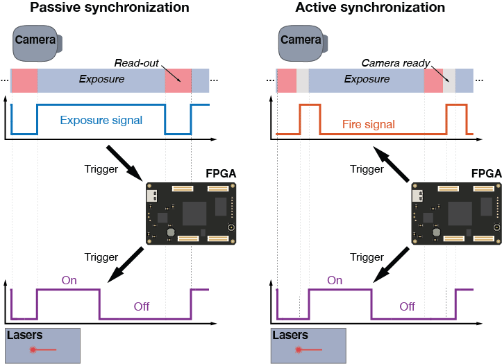
MicroFPGA has two camera modes: PASSIVE and ACTIVE. In PASSIVE mode, the FPGA receives an exposure signal from a camera and processes it to trigger the lasers. In ACTIVE mode, the FPGA generates both fire signal and laser trigger signal. In this case, the fire signal can be used to trigger a camera, and the laser trigger signal is based on an exposure signal that is internal to the FPGA and in sync with the fire signal. We dive more in depth in the Camera triggering section.
Note that the laser triggering parameters are the same in both camera modes (PASSIVE or ACTIVE), and we will therefore describe them first.
Laser triggering
The laser trigger outputs are based on an exposure signal that is HIGH (>2V) when the camera is exposing and LOW (<2V) when the camera pixels are being registered. If the FPGA is in PASSIVE camera mode, the exposure signal must be provided to the FPGA (refer to the pins mapping to identify where to input the signal). Supplying the exposure signal from an external camera can damage the FPGA if the voltage is higher than 3.3 V, see the discussion in the Camera triggering section. In ACTIVE camera mode, the exposure signal is generated internally by the FPGA. Note that there is only one exposure signal, but multiple laser trigger signals generated by the FPGA.
Trigger modes
MicroFPGA offers several laser trigger mode: OFF, ON, RISING, FALLING and FOLLOW. Each mode processes the exposure signal differently. Additional parameters might influence the resulting laser trigger signal in some modes.
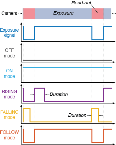
The modes and their parameters are summarized in this table;
| Trigger mode | Parameters | Description |
|---|---|---|
| OFF | The laser is always off | |
| ON | The laser is always on | |
| RISING | duration sequence |
The laser is pulsed for duration μs, on each rising edge |
| FALLING | duration sequence |
The laser is pulsed for duration μs, on each falling edge |
| FOLLOW | sequence | The laser follows the exposure signal |
Trigger parameters
| Parameter | Range | Description |
|---|---|---|
| mode | 0-4 | Sets the laser trigger mode (0=OFF, 1=ON, 2=RISING, 3=FALLING and 4=FOLLOWING) |
| duration | 0-1048575 | Duration of the pulse in μs in RISING and FALLING modes, from 1 μs to 1 s. |
| sequence | 0-65535 | Triggering pattern of 16 bits where each bit correspond to a frame, with the laser being triggered if the bit is 1. |
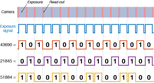
The sequence corresponds to a 16 bits number (0 to 65535) which encodes a trigger pattern in its bits sequence. MicroFPGA reads the binary number from the most-significant bit to the least significant one. If the bit is 1, then the laser will be triggered during the next camera exposure. If it is 0, it will not. The sequence is applied in RISING, FALLING and CAMERA modes. The lasers are synchronized, allowing alternating triggering. The sequence parameter is used to performa alternating triggers, where multiple lasers are triggered on different frames.
Trigger sequence examples
| Decimal | Binary | Description |
|---|---|---|
| 0 | 0000000000000000 | The laser is always off |
| 65535 | 1111111111111111 | The laser is on at every frame |
| 43690 | 1010101010101010 | The laser is on every two frames (starting with on) |
| 51884 | 1100101010101100 | on-on-off-off-on-off-on…etc… |
| Laser1: 43690 Laser2: 21845 |
1010101010101010 0101010101010101 |
Laser1 and Laser2 are alternating |
Use a binary-to-decimal converter to get the sequence right.
Camera synchronization
As mentionned above, MicroFPGA has two camera modes: PASSIVE and ACTIVE. In PASSIVE mode, the exposure signal is provided by an external camera, while in ACTIVE mode the FPGA generates its own exposure signal as well as a fire signal to directly trigger the camera.
PASSIVE mode
PASSIVE mode is activated by setting the camera mode parameter to 0. In such a case, the exposure signal from the camera is supplied too a particular pin (see pins mapping), and there is no other parameter available.
In order to avoid damaging the FPGA, it is paramount to not supplying any signal higher than 3.3 V. For instance, EMCCD often have exposure signals that are 5V, such a signal must be scaled down to 3.3 V before the FPGA, for instance using MicroFPGA SCB board. sCMOS usually run on 3.3 V and their exposure signal can be provided directly to the FPGA.
ACTIVE mode
ACTIVE mode is enabled with the camera mode parameter to 1. The FPGA then generates a fire signal that can be supplied to a camera in order to trigger it. The FPGA also triggers the lasers as previously, albeit using an internal exposure signal. Note that the lasers are triggered regardless of whether the fire signal is actually connected to a camera.
The fire signal is a periodic signal that starts with a short pulse, indicating the beginning of a frame. The exposure signal is synchronized with the fire signal and can be delayed with respect to it. It has a pulse length corresponding to the real camera exposure.
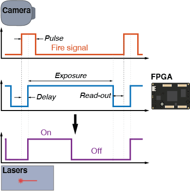
The ACTIVE mode has several parameters that allow users to define both fire and exposure signals: start, pulse, delay, exposure and read-out.
| Parameter | Signal | Range | Description |
|---|---|---|---|
| start/stop | all | 0-1 | Start/stop the synchronization |
| pulse | fire signal | 0-1048575 | Pulse length of the fire signal up to 1 s (steps of us) |
| delay | exposure signal | 0-65535 | Delay between fire and exposure signals, up to 65 ms (us steps) |
| exposure | exposure signal | 0-1048575 | Length of the exposure signal up to 1 s (steps of us) |
| readout | exposure signal | 0-65535 | Delay between end of exposure and beginning of next fire, up to 65 ms (us steps) |
Note the following edge case:
- If pulse > delay+exposure+read-out: then the fire signal is high all the time, the exposure signal is unchanged.
- If delay=read-out=0, then exposure is high all the time! The lasers will not be triggered, unless they are in ON or FOLLOW mode.