MicroFPGA
An affordable and open-source FPGA platform for the electronic control of microscope.
MicroFPGA principle
MicroFPGA is based on the Au, Au+ and Cu FPGAs from Alchitry. Once configured, the FPGA is capable of generating a certain number of signals, as well as reading analog inputs (Au and Au+). It has been used with a variety of devices on multiple microscopes.
The MicroFPGA project is split between multiple Github repositories:
- FPGA configuration
- Complementary electronics
- Micro-Manager device adapter
- Java library
- Python package
- LabView library
Click on the various available signals in order to access more detailed descriptions:
| Name | I/O | Summary | Default number |
|---|---|---|---|
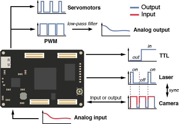
| Camera trigger | Input/Ouput | In PASSIVE mode, the FPGA receives a signal from the camera in order to trigger the lasers, in ACTIVE mode it generates a fire signal for the camera and can trigger the lasers similarly to the PASSIVE mode. | 1 (fixed) |
| Laser trigger | Output | Triggering lasers based on the processing of an exposure signal. Can be used for pattern triggering and/or laser pulsing. | 8 |
| TTL | Output | TTL signals are either HIGH or LOW, and can be used to control devices such as flip-mirrors or switches. | 4 |
| Servo | Output | Servos signals are periodic digital signals (20 ms period and 1 to 2 ms pulses) used commonly to move servomotors. The MicroFPGA servo signals are turned off after 10 ms in order to prevent vibrations. | 7 |
| PWM | Output | PWM signals are similar to the Servo signals, except they are not switched off after 10 s. Together with a low-pass electronic filter, they can be used to produce analog signals, used for instance with AOTFs. | 5 |
| Analog | Input | Analog inputs are limited to 0-1 V and can be used to monitor signals from the microscope, e.g. temperature, laser position, laser power etc. | 8 (fixed) |